Electricity is all around us. It powers our lights, our computers, our microwaves – pretty much anywhere you look you can see things running on electricity! But how does it work? Here we’ll go through how to build a simple electrical circuit that uses a switch to turn on a light in Sparky’s nose.
What you’ll need:
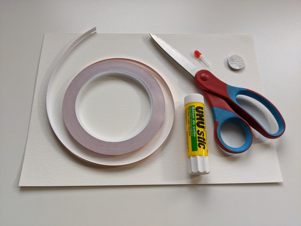
- Printed LED Sparky template (printed single sided)
- 3V coin cell battery (like this, but you can usually find at the dollar store)
- LED (like this LED kit, but you only need one for this project – or contact us to purchase a kit)
- Copper tape (like this one – it’s way more than you need for this project – or contact us to purchase a kit)
- Sheet of card-stock or cardboard
- Scissors
- Glue
First, print out the template and cut out the two sides along the dotted lines. Also cut out the rectangle on the back side – this will be the switch.
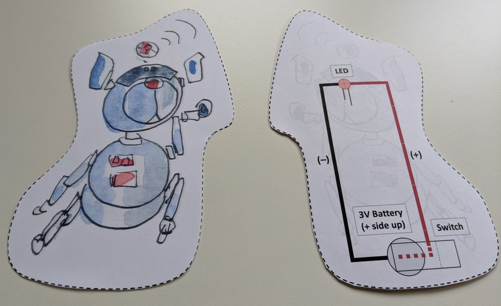
Next, glue one side to the card-stock or cardboard, cut it out, then glue the other side to the back of the card-stock so that it is a single piece.

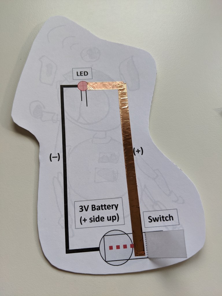
Take a closer look at the back side.
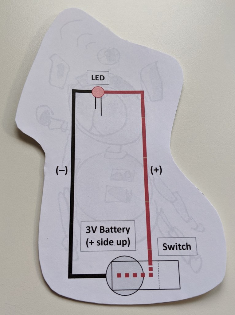
This is an outline of what the electrical circuit will look like. At the top you have an LED, which stands for Light Emitting Diode. This is the load, or the part of the circuit that is being powered. At the bottom you have a battery – this is the power source that is providing the electricity. You’ll notice some red and black lines. These show where the electricity will be flowing through our electrical circuit – from the battery, along the red lines, to the LED, then back along the black lines. Finally, there is a switch. When the switch is closed (or ON) electricity can flow all the way around the circuit turning on the LED. But when the switch is open (OFF), the circuit is broken, electricity cannot flow, and the LED won’t work. We’ll look closer at each of these components as we go through this tutorial.
Poke a hole through Sparky’s nose. This is where the LED will stick through. For now, keep the LED aside since we will attach it later.

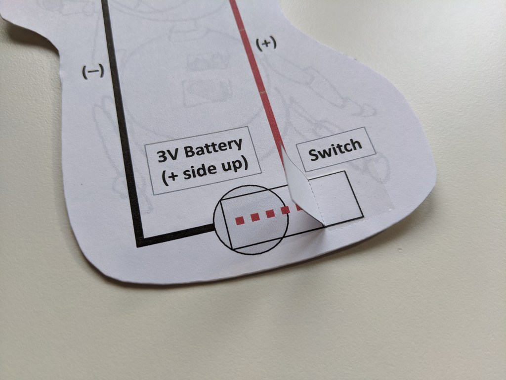
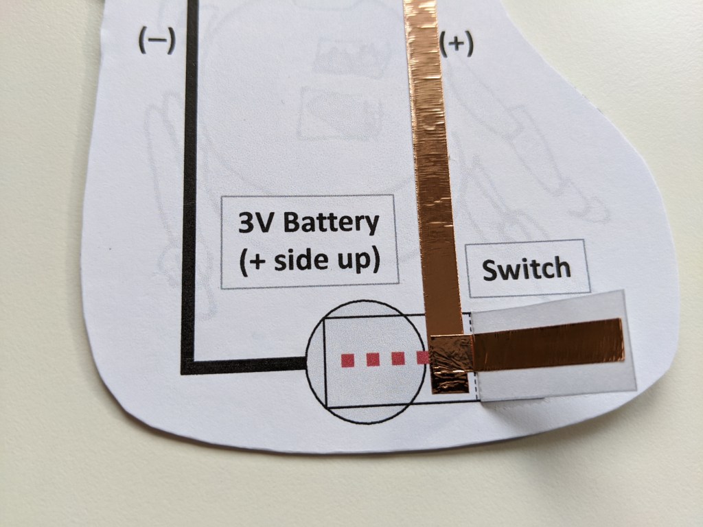
Now flip Sparky over. Fold the rectangular switch along the dotted line, then glue it onto the rectangle at the bottom of the cut-out.
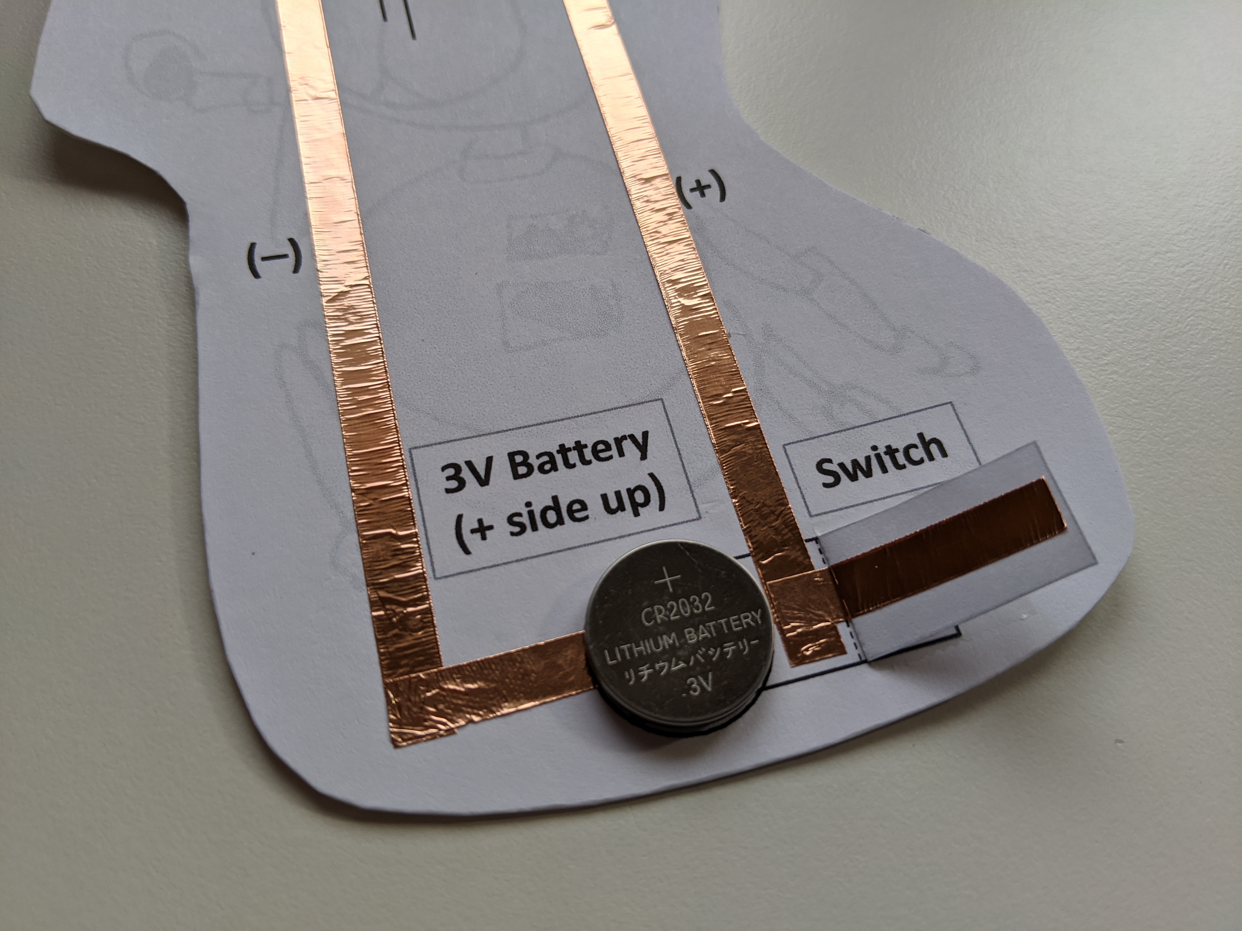
Next, using the copper tape, tape along the red line and onto the rectangle.
Then tape along the switch flap. This competes the positive side of your circuit (where the electricity is flowing from the battery towards the LED).
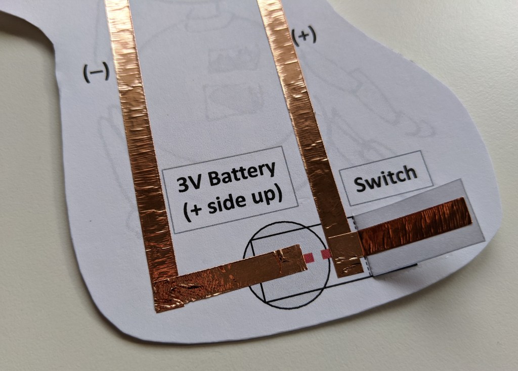
Next, tape along the black line onto the circle for the battery. This will be the negative side of your circuit (where electricity flows from the LED and back to the battery). Be careful that the tape does not connect to the positive side of your circuit.
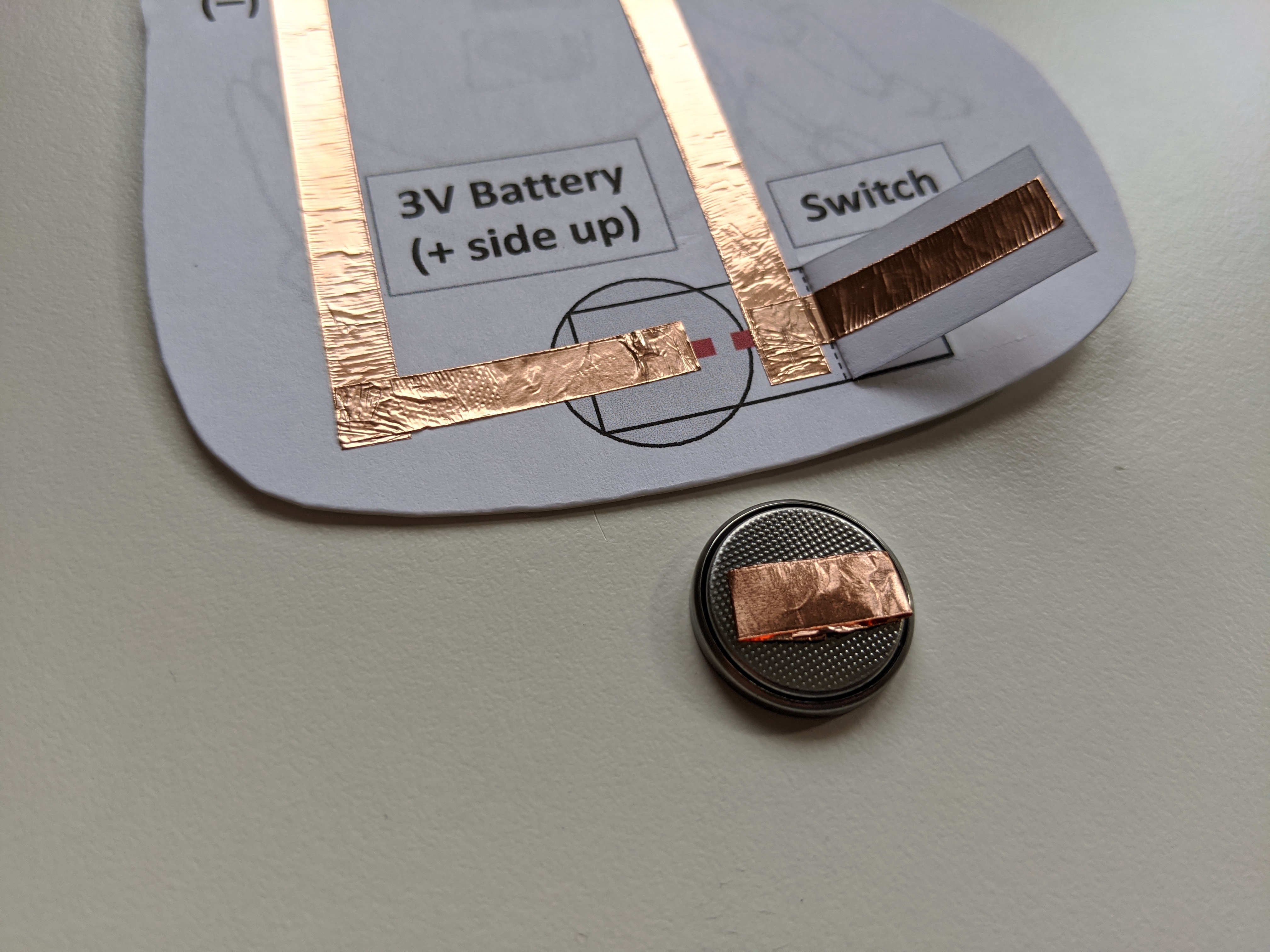
Make a loop of tape and stick it to the negative side of your battery (the side without any writing). Then attach that to the circle on the paper. Make sure that the tape on the back of the battery is connected to the tape on the negative side of your circuit.
And last, but not least, attach the LED! First, poke the LED through from the front side so that the metal legs are sticking through to the back. Make sure that the long leg is pointing to the positive side of the circuit, since the LED will only work if the electricity flows through it in the right direction. Then gently bend down the legs so that they are touching the copper tape.

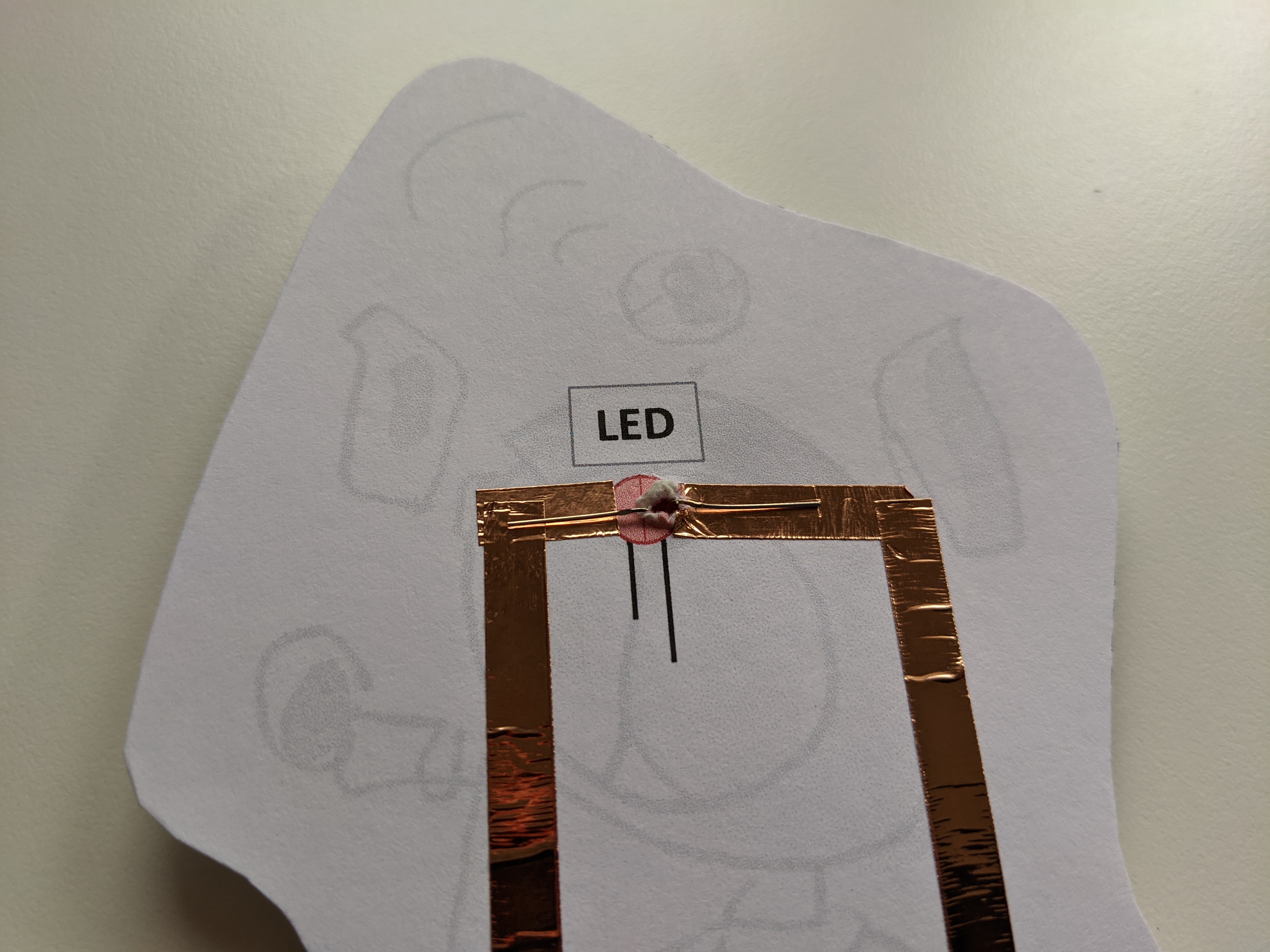
Put more copper tape over the LED legs to make sure you have a good connection.

Now test if your circuit is working! When you close the switch, you should see the LED turn on. If it doesn’t, check that all your connections are taped together properly. If it still isn’t working, try a new LED and/or battery.
Good luck! If you make a circuit we’d love to see some photos and hear your feedback. You could also try making this circuit without the template by drawing your own Sparky (here is a blank template)! If you want to learn more, check out Instructables – this is a neat website full of DIY projects and electronic circuits, and was the inspiration for this activity. Here’s an example project that takes things to the next level. This activity is based on the book If: Ball, Then: Catch.
